STEP2G
If you have BRL-CAD installed on your system, there will be a 'step-g' command, which will allow you to convert STEPfiles i.e. those in .step and .stp file-formats to .g i.e. database of BRL-CAD. Usage: step-g -o outfile.g infile.stp In this tutorial, we will visualize a sample .stp file.
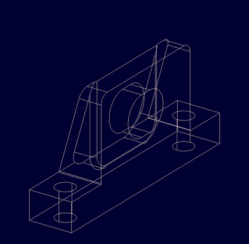
Consider this .stp file. You can copy the data from this file to your working directory and name it bull.stp. We have the output how it should look as below.
After you have bull.stp and BRL-CAD, just type the following command on terminal. " step-g -o bull.g bull.stp "
If it was successful, a file named bull.g will be created and you can view it in mged/archer.
" archer bull.g " or " mged bull.g "
For archer, just right click on 'None'0.r under Tree on left pane and select Wireframe.
For mged, type the command mged> " draw 'None'0.r " on the command window of mged.
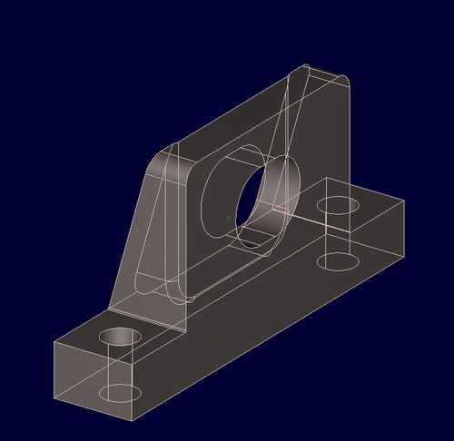
You will see the outline for model bull.g created which would look as follows :-
And to see the model, just raytrace it.
For mged, go to File -> Raytrace. This will open a dialog box named Raytrace Control Panel . Click on 'Raytrace' button.
For archer, in the top pane after menu bar, there will be a camera looking button which will read 'Raytrace the current view'. Click on that.
To remove the wireframe, in mged in the Raytrace Control Panel, there is menu called Framebuffer, select overlay from it.
In archer, in the same pane as Raytrace current view, there will a option called, 'Change Framebuffer Mode' just besides raytrace. Click on that.
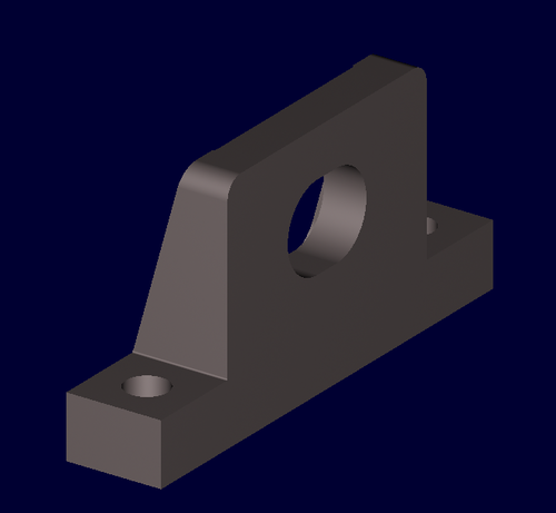
Final View is -
which is similar to that we saw before-


