Difference between revisions of "Extrude"
From BRL-CAD
| (8 intermediate revisions by one other user not shown) | |||
| Line 2: | Line 2: | ||
{|align="right" | {|align="right" | ||
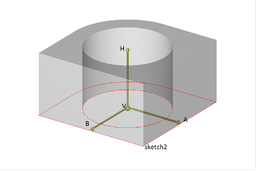
| − | |[[Image:extrude_example.png| | + | |[[Image:extrude_example.png|resize|256px|Example extrude object created with "in" command]] |
|} | |} | ||
| + | |||
| + | |||
| + | You can create an "extrude" object through the normal object creation facilities. | ||
| + | You can either run the "in" command or use the Create menu. The 'in' | ||
| + | command will interactively prompt you for parameters. | ||
| + | |||
| + | Here is an example of a sketch creation followed by an extrude object | ||
| + | creation based on it. | ||
| + | |||
| + | Sketch creation: | ||
| + | <pre> | ||
| + | mged> put sketch_example sketch V {0 0 0} A {1 0 0} B {0 1 0} VL { {0 0} {1 0} {1 1} {0 1} } SL { | ||
| + | {line S 0 E 1} {line S 1 E 2} {line S 2 E 3} {line S 3 E 0} } | ||
| + | |||
| + | </pre> | ||
| + | |||
| + | followed by an Extrude creation: | ||
| + | |||
| + | <pre> | ||
| + | mged> in | ||
| + | Enter name of solid: extrude_example | ||
| + | Enter solid type: extrude | ||
| + | Enter X, Y, Z of vertex: 0 0 0 | ||
| + | Enter X, Y, Z of H: 0 0 1 | ||
| + | Enter X, Y, Z of A: 1 0 0 | ||
| + | Enter X, Y, Z of B: 0 1 0 | ||
| + | Enter name of sketch: sketch_example | ||
| + | </pre> | ||
Latest revision as of 17:40, 5 December 2017

|
You can create an "extrude" object through the normal object creation facilities.
You can either run the "in" command or use the Create menu. The 'in'
command will interactively prompt you for parameters.
Here is an example of a sketch creation followed by an extrude object creation based on it.
Sketch creation:
mged> put sketch_example sketch V {0 0 0} A {1 0 0} B {0 1 0} VL { {0 0} {1 0} {1 1} {0 1} } SL {
   {line S 0 E 1} {line S 1 E 2} {line S 2 E 3} {line S 3 E 0} }
followed by an Extrude creation:
mged> in
Enter name of solid: extrude_example
Enter solid type: extrude
Enter X, Y, Z of vertex: 0 0 0
Enter X, Y, Z of H: 0 0 1
Enter X, Y, Z of A: 1 0 0
Enter X, Y, Z of B: 0 1 0
Enter name of sketch: sketch_example